New 3 Wheeler Model
Body
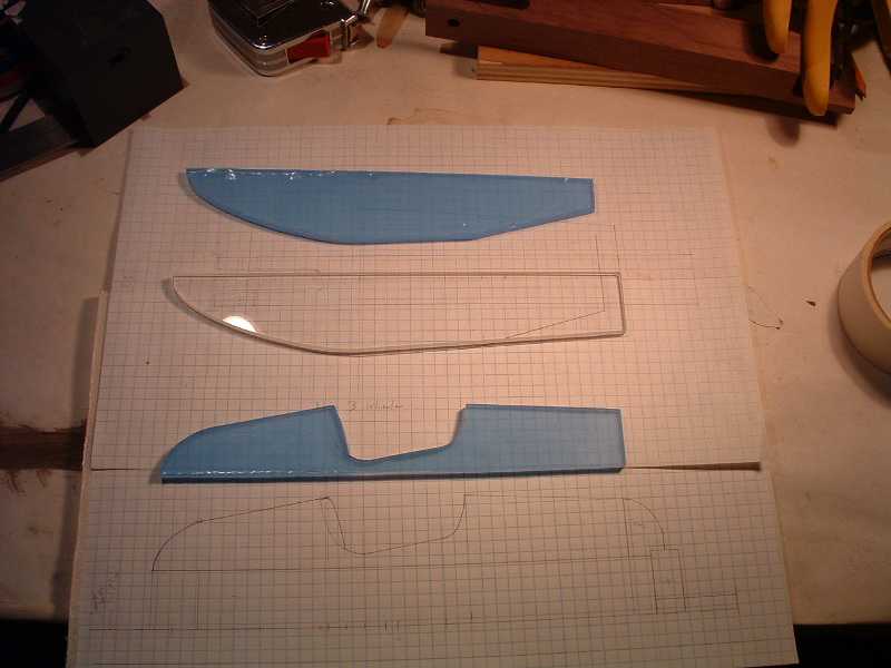
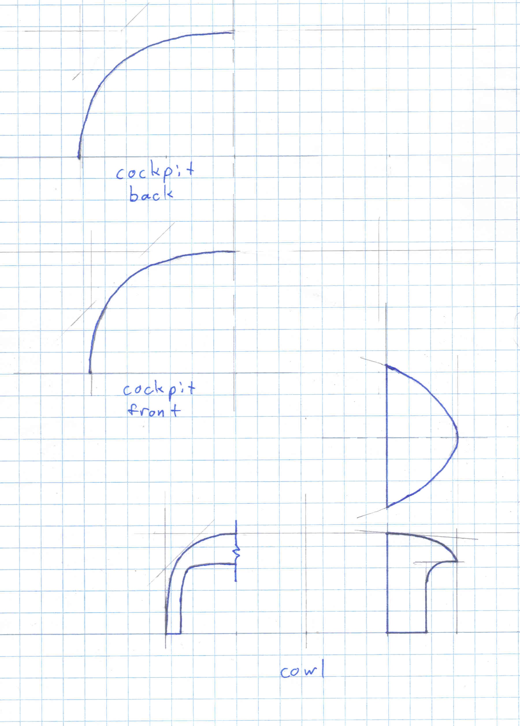
Templates:
Cut three plastic body outline templates from the plan to make it easy to draw the cutting lines on the wood.
Cut body blocks
I started with a 4" x 6" beam of rough cut Black Walnut.
- Cut a block 12" long.
- Band saw two blocks from the 4x6, each 2" thick by 4" wide and 12" long.
- Using a bench top thickness planer, dimension the lower body piece to 1 1/8" thick, the upper body piece to 1 5/8" thick and square the sides of the blocks.
- I ran the faces of the blocks that would get glued together over some sand paper clamped onto a flat piece of plywood to take off any texture left by the power planer.
-
Addendum:
It will save some agony at glue together time if you drill two or more holes for dowels through the lower body piece and 1/8" into the upper piece. Put them just in front of and just behind the cockpit and on each side. Set them about half way between the chassis slot and the side.
Band saw the basic body shape
- Mark the centre line on the top face of each body piece. (On the lower body piece put centre punch marks or some permanent mark on the centre line so you can find it later when cutting the chassis slot.)
- Mark the outline of the sides on the top of each piece using its template aligned on either side of the centre line.
- Mark the top outline on the side of the top block using its template, aligning the rear of the template with the rear of the side cut markings on the top of the block.
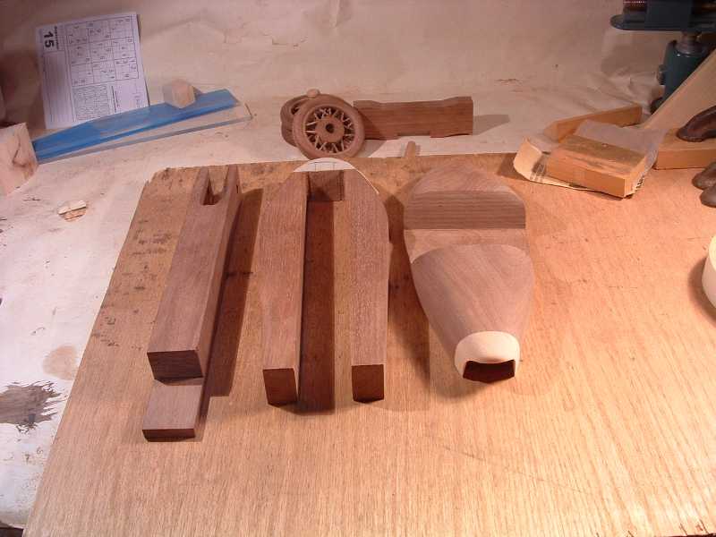
- Cut off the sides of each block on the band saw. (Keep the cut-offs.)
- Tape the sides pieces back onto the top block (without covering the top cutting lines) and cut off the top on the band saw. Start with a short cut down the seat back, back out the saw, then cut into the front of the cockpit and continue around to the first cut. Then the bonnet and tail are easy cuts. (Again keep the cut-offs you will need them later.)
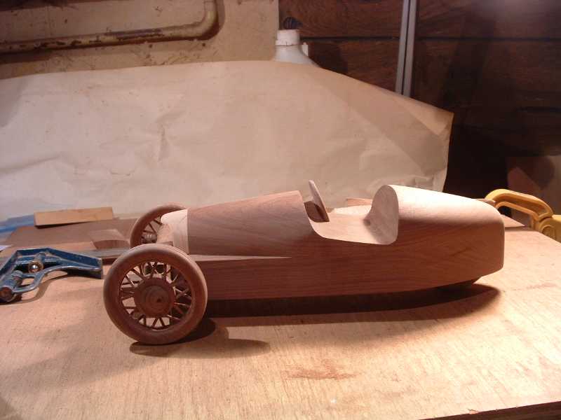
You might notice in the pictures that I cut the slot in the lower body for the chassis at this time. If you have any concern about the wood splitting while you plane and sand the sides I recommend waiting to cut it when all the shaping and smoothing is done and you are ready to glue the body together.
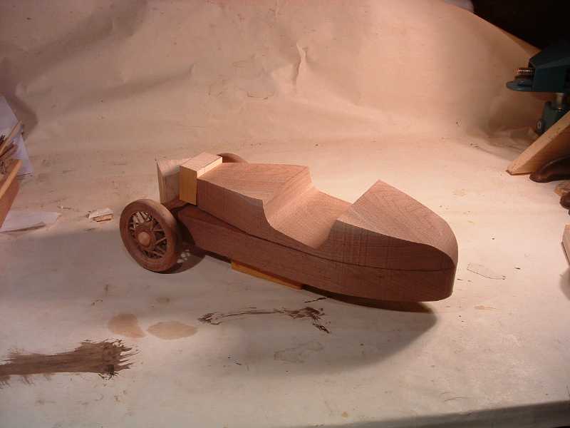
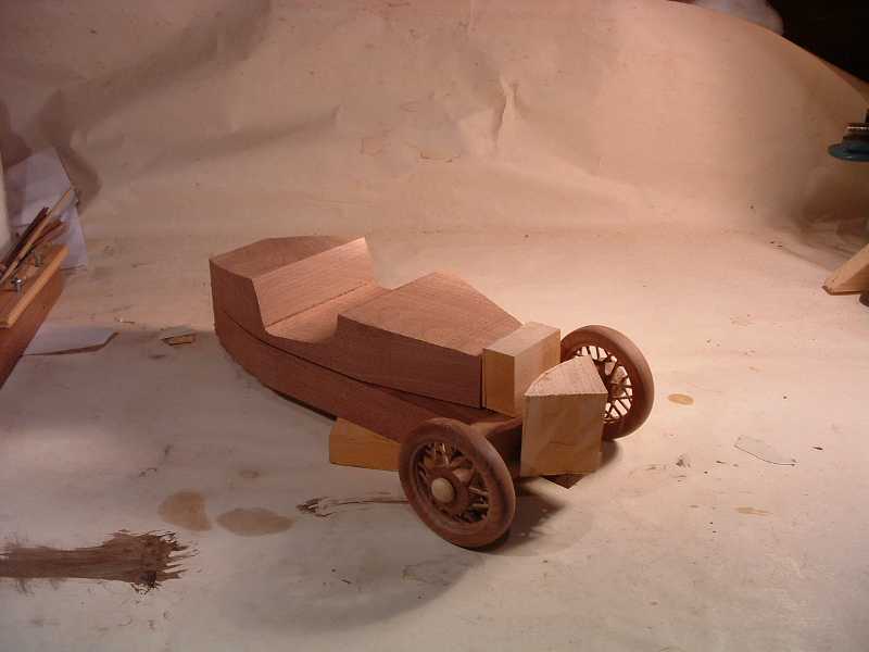
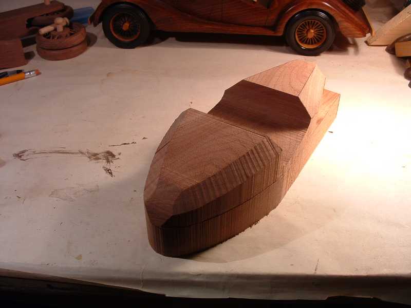
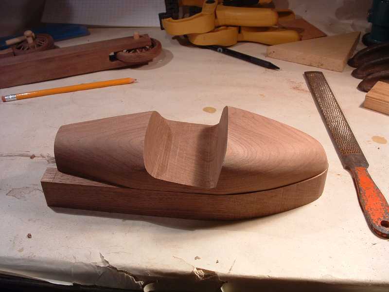
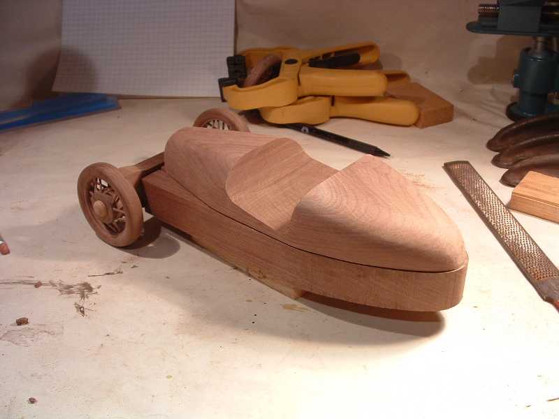
Here is an idea of what it is going to look like
To speed up the shaping we will cut a 45 degree bevel along each side of the top.
- Mark straight lines along the bonnet from 3/4" in from the sides at the front of the cockpit to 3/8" in from the sides at the cowl.
- Mark 7/8" in from the sides at the back of the cockpit and draw curves from these points following the body sides back to the tail.
- set the band saw at 45 degrees and cut off the bevels.
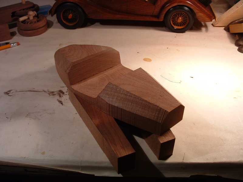
Your bevels will look wider than those pictured, I miss judged the body's cross section curvature in my initial plans.
From the plans, cut out cross sections for rear and front of cockpit, and for the joint with the cowl.
I used a Jack Plane and a little thumb plane to shape the body.
Smooth out the plane's marks with a wood file
Sand the body with 100 grit on the palm sander.
Use a drum sander in the drill press to sand off saw marks from the sides of the lower piece. Sand top face of the lower body piece with 150 grit paper clamped down on a flat piece of plywood (to keep it flat for gluing)
Cowl
- Cut a block of the hop hornbeam; 1 1/2" high x 2" wide x 1" deep.
- Draw the cowl outlines on the front, side, and top of the block.
- Use the band saw to cut the three profiles, taping back the cut-offs from the first two directions to keep things square for the following cuts.
- Use the drum sander in the drill press to shape the cowl.
- Glue the cowl onto the upper body.
- Smooth the cowl into the body with; file, sanding block, and palm sander.
Chassis Slot and Rear Wheel Well
- Mark out the slot in the lower body for the chassis. The back of the motor mount lip aligns with the front edge of the lower body piece. Fit a wheel onto an axle pin in the chassis wheel slot to see how much further back you must cut the body piece in order to clear the wheel.
- I wrapped the tail with masking tape to reinforce it while cutting it.
- Cut the chassis slot on the band saw.
- Mark the rear wheel-well area on the under side of the top body piece. Use the bottom piece and the chassis as guides.
- Using a 5/8" Forstner bit in the drill press with the drill press stop set to prevent the bit from reaching the table by about 1/4" drill out the wheel well. Use a chisel to smooth off the bumps between drill bores. Check the well's depth using the wheel mounted in the chassis. If it spins freely when they are upside down your are done. Raise the drill press table a little if the wheel does not turn freely and drill some more.
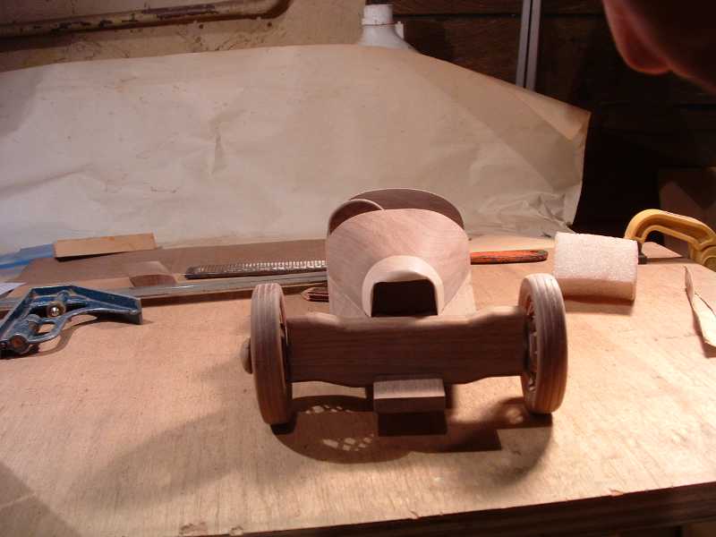
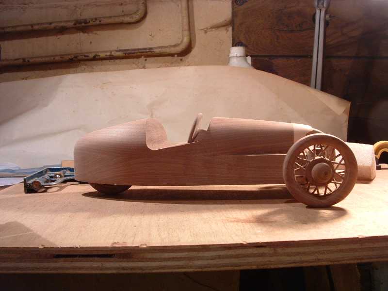
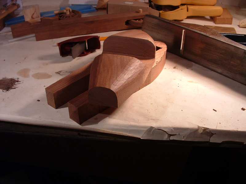
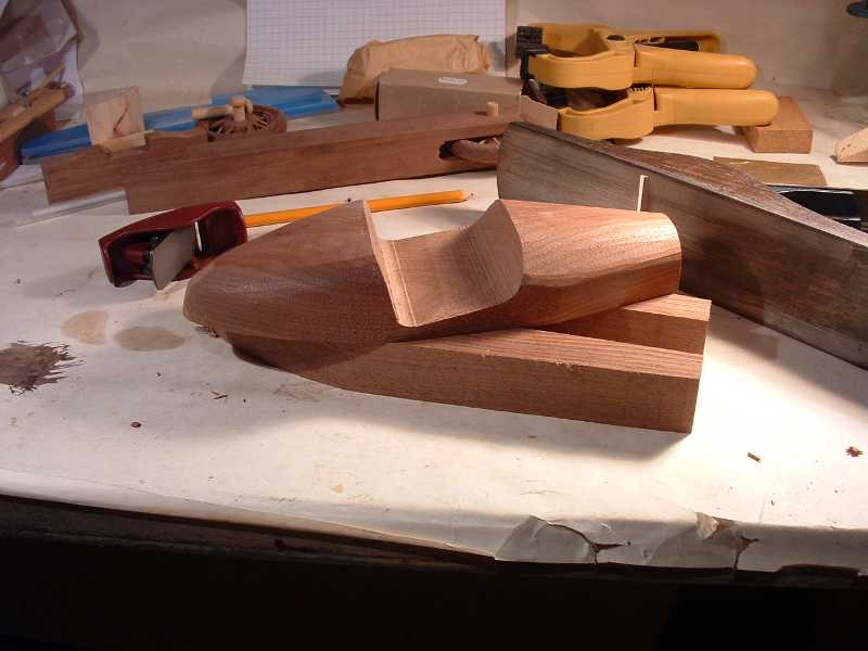
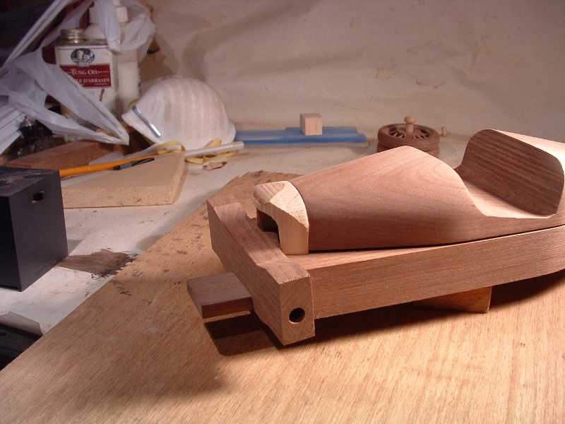
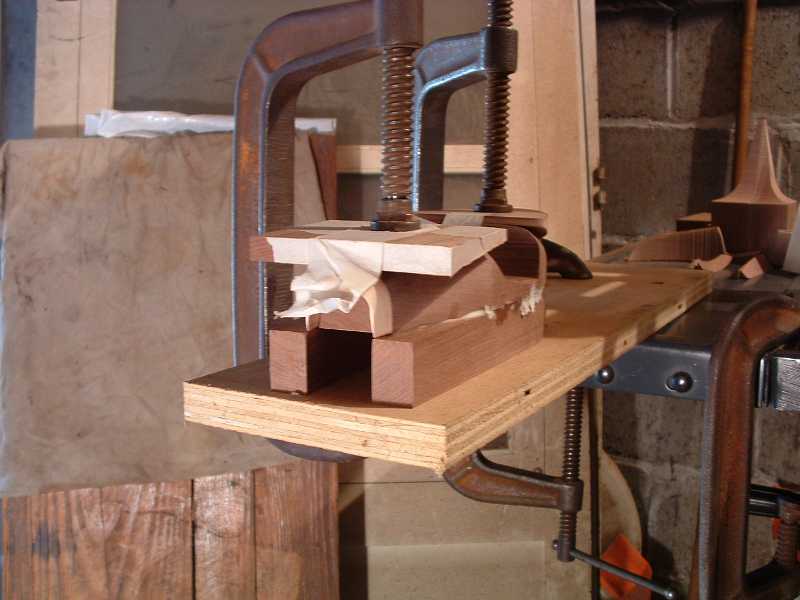
Almost ready to assemble:
Assembly
- Insert your alignment dowels.
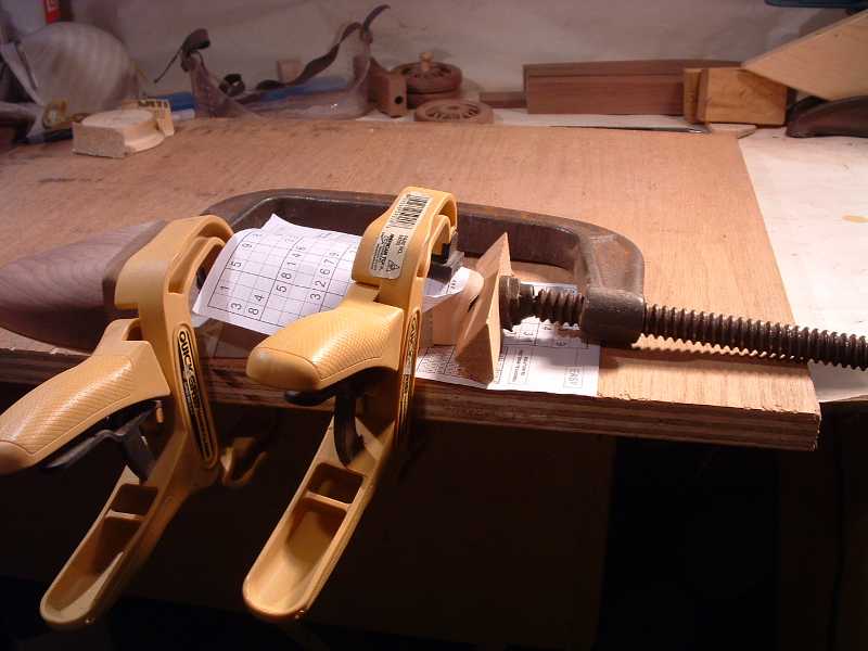
- Wrap a couple of layers of newspaper around the chassis piece and slip it into the front 1/2" of the lower body to keep the sides from pinching in.
- Glue and clamp using the top cutoffs from the bonnet and tail under the clamps.
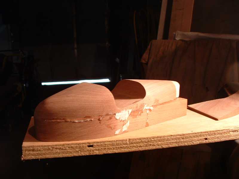
(This is when more pictures of the new three wheeler became available and I saw that I had made the top too flat across the front and rear of the cockpit. So back to the planes to reshape the cross section.)
Sand the body ready for applying finish
- Drum sand off the glue beading with coarse, then do sides of lower body with medium and fine.
- Use palm sander with 100 grit to touch up the curves flattened by the drum sanding.
- Then go over it all with the 150 grit sandpaper in the palm sander.
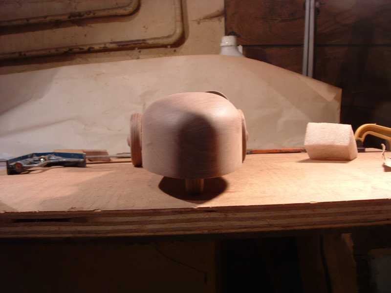
- Finally hand sand with the 150 grit. I finished rounding the beetle back by using strips of the sand paper which I draped over it and then pulled back and forth (as in buffing leather shoes with a cloth) across the dome in various directions until the flat spot disappeared.
- Use the cut off from the cockpit as a sanding block and hand sand out the saw marks in the cockpit.
Steering Wheel
Use the material cut out of the cockpit to make a steering wheel the same way as is shown for the Plus 8 model, using 18 degrees for the angle of the wheel's tilt and a diameter of 1 7/16", it is 9/16" from the dashboard to the face of the steering wheel.
Waiting to go to the paint shop