New 3 Wheeler Model
Design
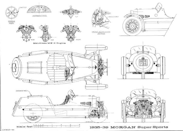
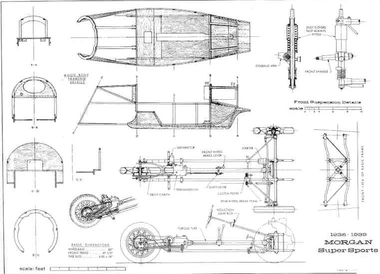
The 'build a trike' bug bit me when MMC announced they would introduce a new three wheeler at the 2011 Geneva auto show. I found two pages of drawings on GoMoG:
And decided to give it a go.
Wheels:
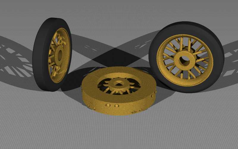
One problem I had to overcome before starting was the design of the wheels. A trike's wire wheels stick out in front so they have to look good and look like wire wheels from both sides. Cutting some grooves on store bought wheels like I did on the Plus 8 model would not do. Store bought spoke wheels have radial spokes not the crisscrossed spokes of wire wheels. I had to design something new.
My design tool of choice is a ray tracing program called Povray.
With it you code a scene using commands like; 'box', 'cylinder', 'sphere', and 'cone'. You make more complex shapes when you 'union' these together and 'difference' them away from each other. You can apply a 'texture', with some colour 'pigment'. Then 'rotate' your object around the x, y, and z co-ordinates and 'translate' it to its location. Set one or more 'light_source' and position and aim a 'camera'. Then you feed your coded file into the povray program and out comes a picture of your scene, no drawing skill required!
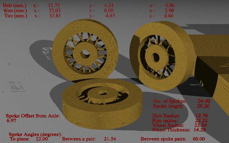
I set up a spreadsheet to do the calculations of spoke angles and positioning. Then used those numbers in the povray code and tried out several numbers of spokes and a couple of lacing patterns. Another handy povray command was 'intersection', using it to combine the spokes showed something only if the spokes intersected, which of course they did at first. Once I adjusted the spokes to show nothing I switched the 'intersection' to 'union' to show the spokes that now ran clear of each other.
A pattern using 20 spokes gave a good hint of the wire look without looking too labour intensive. But then I visited a three wheeler owner to see one with my own eyes and realized I had to give the hub a larger diameter. That meant I would need to make changes to both the spreadsheet and my wheel povray file to see the results. Being a retired computer programmer I opted instead to make major changes to the wheel povray code so it would do the calculations and I could dispose of the spreadsheet.
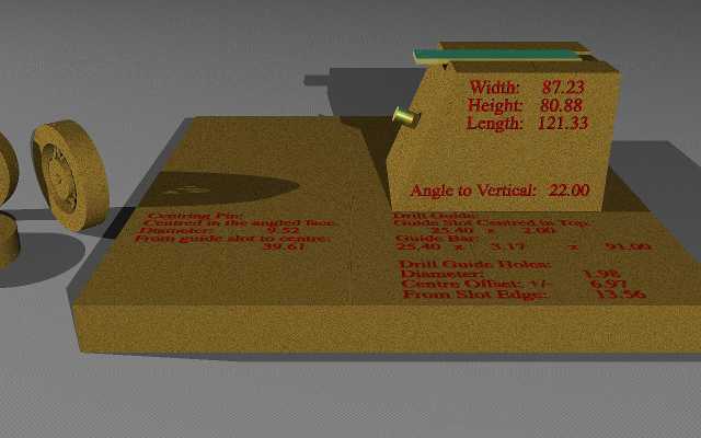
While I was developing the computer model I was brain storming with my nearest fellow Morgan owner, Al, about how to build the real model wheels. We came up with an idea for a jig to use when drilling the holes the spokes will go through. It would hold a wheel disk at the correct tilt to the drill so the spokes would go through the centre line of the inner rim and enter the hub just inside the edge. And it would have drill guides to guide the drill at the correct offset from the axle. Since the tilt and offset for the jig were numbers I was now calculating in the povray code for the wheels, I added code to also create the jig. As I studied the povray documentation I learned to display text in my pictures which now list the dimensions and angles to use in the construction.
After adjusting the model's wheel diameter to be in scale with the Plus 8 model and setting the inner rim and hub diameters to the nearest tool diameters, I found that 24 spoke wheels looked good.
And the jig to build them
Chassis:
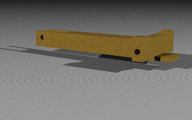
I measured the wheel base and track width from the diagram on GoMoG and scaled them up to the wheel size. Then in another povray file coded a central chassis member with a slot in the back for the rear wheel and a shelf in front for the motor mount. The cross frame was a solid piece shaped like the cross frame with a dip in the middle made thick enough to hold the wheel axle pegs.
Engine:
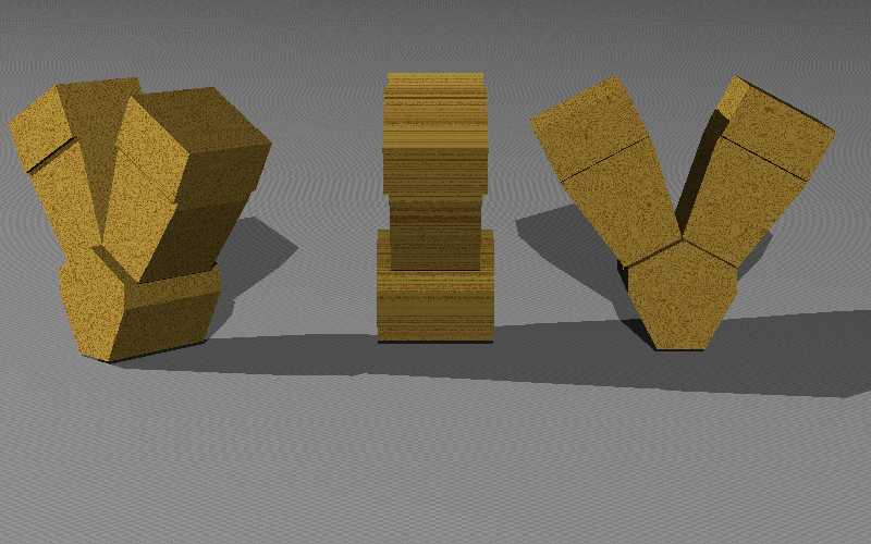
My first thought was to make a 'toy' version of the Matchless engine seen in the drawings using various diameter dowels:
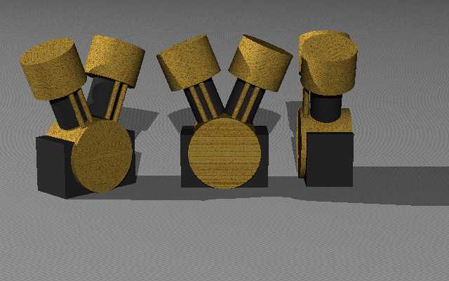
But I also 'toyed' with the idea of making the New Morgan Three Wheeler with the S&S engine:
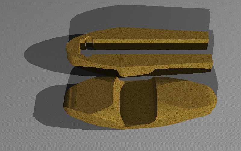
Body:
First off this model would be in stripped down for racing mode, i.e. no windscreen and no wings to fiddle with.
Barrel Back?
Or new Beetle Back?
I decided on the new trike since the lower part of the body does not slope down at the front. Meaning the body could be made with two flat boards and all the hand shaping work would be restricted to just the top piece. Here is how they would look after the rough cutting on the band saw.
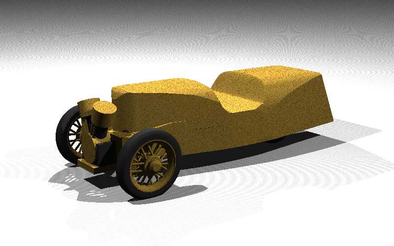
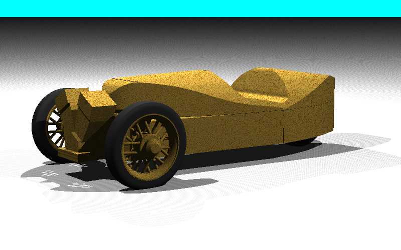
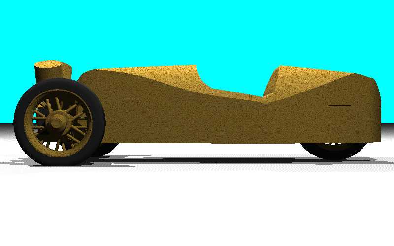
The Computer Model:
Side:
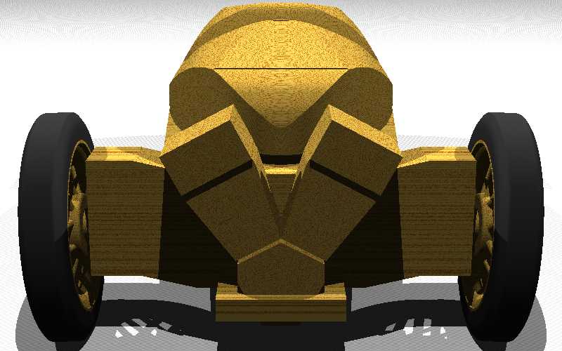
Front:
Rear:
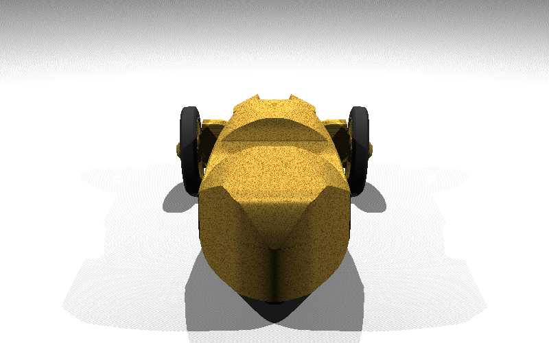
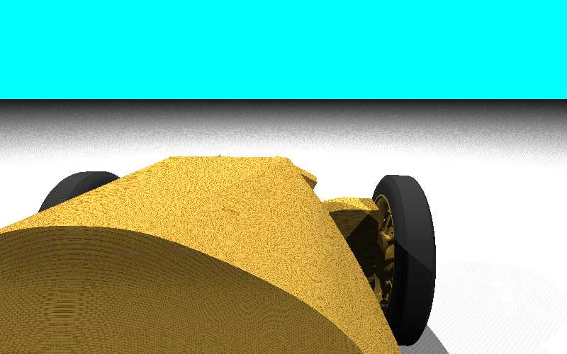
Looking over the bonnet:
There will be jigs:
Before I would tackle this job I had to assure myself I had ways of holding the work pieces and ensuring that the correct cut will be made each time. The jigs that need to be made are:
1. A zero clearance table saw insert, if like me, you cannot find a commercial version for your saw.
2. Dowel making jigs.
3. The spoke hole drilling jig shown above.
4. A wheel clamp that you clamp onto the drill press table after centring it to hold the wheel disks as the hubs and inner rim are cut out.
